A Comprehensive Guide for Using CANopen Protocol to Intereface with the Invertek Optidrive P2 Variable Speed Drive.
The CANopen is a protocol that is widely used in industrial automation to maintain and manage a complex network of a variety of devices, in order for them to work efficiently and coherently. The following guide dives into the details on how to utilise the CANopen protocol to communicate with an Optidrive P2 VSD, both reading and writing data to and from the device, in order to control the drive effectively.
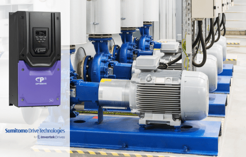
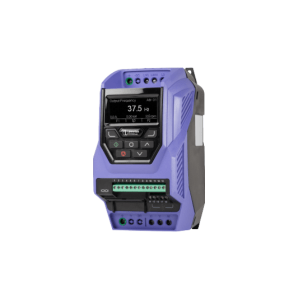
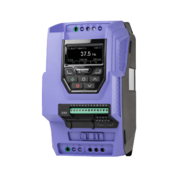
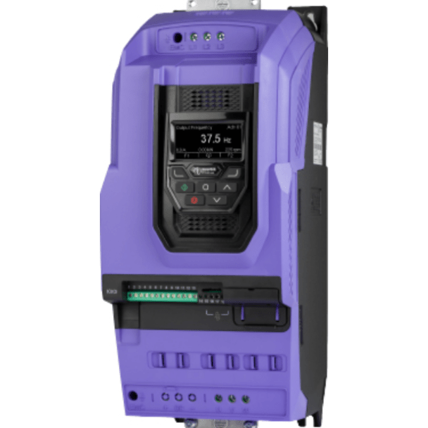
The advantage of the P2 drive is that it comes equipped with an RJ45 port that supports CANopen interface. The port is not an optional extra, but a standard default.
1. Setting Up the Optidrive P2 VSD for CANopen Communication
In order to enable the CANopen communication, the Optidrive P2 VSD, the following steps are provided:
Enable CANopen Communication: Parameter P1-12 set to 6. This is the parameter that switches the drive's communication to the CANopen protocol. This will enable the device to communicate within a CAN network.
Configure Baud Rate: P5-02 is the parameter that allows the user to set the desired baud rate. 125kbps, 250kbps, 500kbps, and 1Mbps are the options available. The baud rate should match the settings on the other devices that are on the CAN network, so that seamless communication is ensured.
Physical Connection: Use the RJ45 port with the following pin configurations:
- Pin 1 CAN - : Negative data line for CAN communication.
- Pin 2 CAN + : Positive data line for CAN communication.
- Pin 3 0 Volt : Ground reference.
- Pin 4 Optibus / Remote Keypad / PC Connection -
- Pin 5 Optibus / Remote Keypad / PC Connection +
- Pin 6 +24 Volt Remote Keypad Power Supply : Provides power to connected peripherals like keypads.
- Pin 7 RS 485- Modbus RTU
- Pin 8 RS 485+ Modbus RTU
Once the above parameters are configured and the device is connected to a CAN network, it should be ready to send and receive messages for control and monitoring.
2. Essential Parameters for CANopen Communication
For effective communication, it is important to know and understand the key parameters and their functions. The following is a list of COB-ID and their functions:
- Network Management (NMT): This manages the overall network state, which includes the start, stop, and rest commands. NMT commands can be used to communicate with the drive to bring it online or reset it after it faults.
- Synchronous Message (Sync): COB-ID 080h is configurable, which allows the synchronisation of actions of all the devices on the network, making sure the control is coordinated.
- Emergency Messages: COB-ID 080h + Node Address. This is used to communicate critical errors or faults, which allows for an immediate response to the corresponding issues.
Process Data Objects (PDO) :
- PDO1 (TX): COB-ID 180h + Node Address. This transmits real-time process data from the drive. This could relate to the speed and torque of the drive.
- PDO1 (RX): COB-ID 200h + Node Address. This receives the process data commands from the network, like speed references and control commands.
- PDO2 (TX): COB-ID 280h + Node Address. This is used to transmit additional data. This is pre-mapped, but it is disabled by default.
- PDO2 (RX): COB-ID 300h + Node Address. This is for additional data reception for more advanced control.
- Service Data Objects (SDO)
- SDO (TX): COB-ID 580h + Node Address. Transmits service data, used for non-time-critical communication like configuration.
- SDO (RX): COB-ID 600h + Node Address. Receives service data from the network, allowing parameter adjustments.
Note: The Optidrive P2 is only able to support expedited transmission via SDO, and is only able to manage up to two PDOs. Expedited transmission is sent in a single CAN frame, which allows for smaller and faster transactions.
3. Using CANopen Communication to Control the Drive
To control the Optidrive P2 VSD using CANopen, you will primarily interact with the Control Command Register (2000h) and Speed Reference (2001h).
Here's how to use these registers effectively:
In order to control the Optidrive P2 drive using CANopen, the user will be interacting with the Control Command Register (2000h) and Speed Reference (2001h). The following shows the process of using these registers effectively.
- Starting the Drive:
- When Bit 0 (Run) is set on the Control Command Register (2000h), this initiates the drive to start, provided that all conditions are met (meaning there are no faults in the system)
- Example: Sending a value of 0x0001 will start the drive.
- Stopping the Drive:
- In order to stop the drive immediately, Bit 1 needs to be set on the Control Command Register.
- If the drive needs to come to a stop gradually without braking, then Bit 3 needs to be set.
- Resetting Faults:
- Setting Bit 2 (Reset) clears any faults if the drive is in a fault state. This is an edge-triggered setting, so toggling the bit from 0 to 1 will carry out the reset.
- Adjusting Speed:
- Write to the Speed Reference (2001h) register to control the drive speed. The value is in Hz with one decimal place. For example, writing 500 sets the speed to 50.0 Hz.
- The value is in Hz with one decimal place. Which means if you write 500, then the speed is set to 50.0Hz.
- Example: To set the speed to 30.0 Hz, write 300 to 2001h.
- Monitoring Drive Status:
- Read from the Drive Status Register (200Ah) to monitor the drive's current state. Bit 0 indicates if the drive is running, and Bit 1 shows if a trip (fault) has occurred. Bits 8-15 display any active error codes.
- To monitor the drive status, we need to read the Drive Status Register (200Ah). Bit 0 indicates if the drive is running, and Bit 1 indicates if a trip or fault has occurred. Any active error codes are displayed by Bits 8-15.
4. Common Error Codes
To troubleshoot properly, a good understanding of the error codes is needed. Here are the following frequent fault codes and their meanings:
- 00 (No Fault):
- The drive is in proper operation mode without any errors.
- The drive is in proper operation mode without any errors.
- 03 (Instantaneous Overcurrent):
- There has been a current spike beyond safe limits.
- There has been a current spike beyond safe limits.
- 06 (Overvoltage on DC Bus):
- The maximum DC bus voltage has exceeded the maximum threshold.
- The maximum DC bus voltage has exceeded the maximum threshold.
- 07 (Undervoltage on DC Bus):
- Voltage on the DC bus has dropped below the minimum threshold.
- Voltage on the DC bus has dropped below the minimum threshold.
- 08 (Heatsink Over Temperature):
- A protective shutdown has initiated as the drive's heatsink has overheated.
- A protective shutdown has initiated as the drive's heatsink has overheated.
- 14 (Input Phase Loss Trip):
- One of the input phases is missing, which can cause improper drive operation.
- One of the input phases is missing, which can cause improper drive operation.
- 51 (CANopen Communication Loss Trip):
- Loss of communication between the drive and the CANopen network, may have been caused by wiring issues or configuration errors.
When a trip occurs, these codes are presented in the high byte of the drive's status word. This makes it easy to identify them during diagnostics.
5. Basic Parameter Selection via CANopen Communication
The SDO channel provides access to the parameters, which allows users to read and write their configurations. Here are the following parameter groups:
- Group 1 (P1-xx): Basic drive settings for speed and control.
- P1-01 (2065h): Maximum Speed/Frequency.
- This parameter sets the upper speed limit of the drive. For example, a value of 3000 represents 50.0Hz.
- P1-02 (2066h): Minimum Speed/Frequency.
- This parameter sets the lower speed limit for the drive, so that the drive does not drop below a safe operational speed.
- P1-03 (2067h): Acceleration Time.
- This sets how the drive quickly ramps up to the desired set speed. A value of 300 corresponds to 30.0 seconds.
- P1-01 (2065h): Maximum Speed/Frequency.
- Group 2 (P2-xx): Preset speeds and analog output configurations.
- P2-01 (20C9h): Preset Speed 1.
- This parameter simplifies repetitive tasks by allowing quick selection of predefined speeds.
- P2-11 (20D3h): Analog Output 1 Function Select.
- This parameter configures what is put as an output through analog output 1. This could be motor speed or torque.
- P2-01 (20C9h): Preset Speed 1.
For reading/writing parameters:
- Read Example: To retrieve the maximum speed setting, send an SDO read request to Index 2065h.
- Write Example: To modify the maximum speed, send an SDO write request to Index 2065h with the desired value.
Note: CANopen configurations revert to default settings after a power cycle unless explicitly saved using the appropriate parameter settings.
Conclusion
Integrating the Optidrive P2 with a CANopen network offers robust and flexible control capabilities. By understanding the setup process, essential parameters, bit-level operations, common error codes, and parameter management, users can efficiently manage and control drive operations within their automation systems.
If you have any questions or need some support in enabling your Optidrive P2 Variable Speed Drive with CANopen communications, give the ADM team a call on 1300 236 467 or send your question to our contact page here.