Designing a PLC Program Using the OptiTools Studio for Invertek VSDs
Programmable Logic Controllers (PLC) are frequently used to control industrial machineries that utilise variable speed drives (VSDs) to control motor speed.
The OptiTools Studio is a powerful, user-friendly PC-based software designed by Invertek to set up, monitor and control its VSDs. This software allows users to create, test, execute, modify and simulate PLCs with function blocks — reusable codes that have memory and same input values that can provide varied results. Invertek VSD P2 models have built-in PLC, which can be configured using the OptiTools Studio.
The software-generated designs can be transferred to an OptiStick, P2 / HVAC drive, or a data file for the VSD. The OptiTool software also has a security feature so that designs are safe from unauthorised access to PLC program designs.
If you require assistance or have any questions about the OptiTool Studio, contact our team.
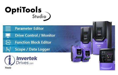
What are the Key Features of the OptiTools Studio for PLC Programming?
The following features help make PLC programming with OptiTools Studio easy.
Function Block PLC Editor: Use the drag-and-drop interface to establish links between logic and data variables.
Graphical Simulator: Real-time verification and testing of the functioning of PLC programs.
Drive Configuration: Allows users to customise and modify drive parameters for maximum effectiveness.
Secure Program Transfer: When the security function is set, the PLC program transferred to a drive cannot be read out again.
How to Design a PLC Program
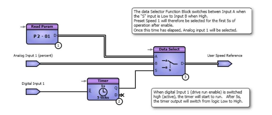
PLC programs are built by dragging function blocks from the library onto the design page. To connect the blocks, left-click and drag connections (net) between inputs and outputs. You can also create branches (net spurs) by pressing the “Shift” key while hovering over an existing net, then dragging to the desired input. During this process, all valid input points will be highlighted in green.
All inputs and outputs to and from the PLC program must use Input or Output blocks. You can select the signal or variable linked to the drive by double-clicking on the Input or Output block, which opens a list of available options.
Once the PLC design is complete, the software can provide statistics such as RAM and Flash usage, determining how efficient the PLC is at the design stage.
How to Simulate PLC Program Functionality
It is essential to use the integrated simulator to test the PLC program before uploading it to the drive during operation. This helps identify any errors in advance, preventing potential damage to physical components.
You can follow this step-by-step process to simulate your PLC program:
Launch the simulator from the toolbar, which will then move your design to the simulation page.
At the simulation page, you can track your outputs and configure your inputs.
Monitor your data values for outputs from the function blocks. The function blocks for data outputs will be displayed above the corresponding nets.
Verify the logic states, which are represented by glowing nets (either red or blue).
Modify the execution sequence numbers as needed.
Exit the simulator mode when your test is done.
Configuring Drive Parameters for a PLC Program
The following drive parameters must be configured to ensure proper PLC functionality.
P6-10 = 1 (Enable PLC program)
P1-12 = 0 (User-defined control of digital and data inputs)
P9-10 = 7 (User Speed Reference as the drive’s speed source)
Adjust digital inputs (e.g., disabling unwanted effects by setting P9-06 and P9-18 to “OFF”)
How to Transfer the PLC Program to a Drive
There are a few ways to transfer the PLC program to a drive. First you need to connect to the PC using Bluetooth or an RS485 cable.
Direct transfer - Transfer the PLC program straight to a connected drive.
Transfer to OptiStick
Save as a data file - with or without serial number constraints, you can save the PLC program for later use.
Operation and Trip Codes
If an error occurs, the drive might trip. If this takes place, a PLC trip code will be displayed while the PLC program is running. Below are some of the typical trip codes that you might encounter.
PLC-01: Unsupported Function Block (e.g., running a program on outdated firmware)
PLC-02: Exceeded program counter limit (prevented by the compiler)
PLC-03: Division by zero error
PLC-04: Upper limit value lower than the lower limit value in function blocks
Keep in mind that when the PLC trips, the entire program is deactivated. This happens because parameter P6-10 is automatically reset to 0 during the trip. To resume operation, you must manually set P6-10 back to 1.