How Vibration Monitoring Works
Vibration monitoring is a tried-and-tested method for monitoring the condition of critical machinery and plant, so you can take preventive measures to avoid costly breakdowns and unnecessary maintenance runs.
Speak to our team on 1300 236 467 or send any questions through our contact page here.
What is Machinery Vibration and How is it Measured?
A body is said to vibrate when it describes an oscillating motion about a reference position.
Velocity and acceleration are the 2 attributes that are most closely associated with vibration.
If we assume that the oscillating motion of vibration is sinusoidal, then there are only 3 questions you need answers to in order to select an accelerometer:
- What is the approximate amplitude of the vibration in millimetres?
- What RPM or frequency does the machine running at during normal operation?
- Do you want to monitor velocity (mm/s), or acceleration (mm/s2 or g)?
The profile of vibration is more complex than a pure sinusoidal waveform, but this is a good place to start, when calculating what accelerometer is required. It is also worth noting that when a smooth-running machine starts succumbing to wear and tear, the numbers are going to get bigger in terms of amplitude and frequency.
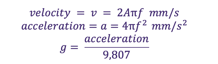
What follows is a brief explanation of how we arrive at the following simple equations to work out the velocity in mm/s and acceleration in g of pure sinusoidal waveforms.
If we can get the amplitude A and frequency f from the customer, then this gives us an idea of the starting point of the measurement range we should be looking at when it comes to recommending the right accelerometer for the application.
Equations to Calculate Velocity and Acceleration regarding Vibration
You can use the following simple equations to work out the velocity in mm/s and acceleration in or mm/s2 g of pure sinusoidal waveforms.
The Mathematics of Vibration Monitoring
Let’s assume the vibration is sinusoidal in nature.
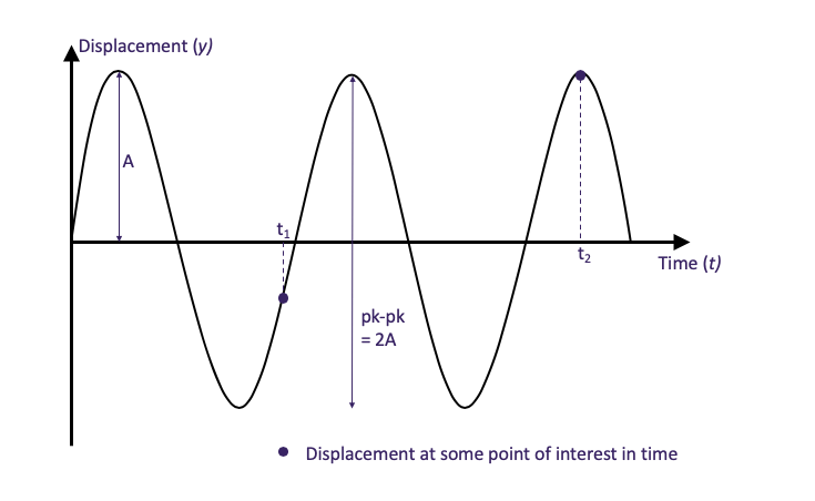
A sine wave is described mathematically by the equation:

Simplifying the Mathematics of Vibration
At this stage, we are not interested in the displacement, velocity and acceleration at a particular instant in time. You just need to know the maximum values of each of these.
The maximum value of a sine or cosine function is 1. So, to find the maximum value of the displacement, velocity and acceleration in the above equations, we let sin(2 pi f×t)=1 and cos(2 pi f×t)=1, so we get the following result:
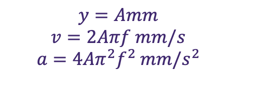
For example, let’s plug in some values and assume your machinery is running at 1,200 RPM (frequency = 20 Hz) and the peak to peak vibration is 2 mm, therefore A=1.
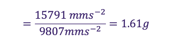
Our answers to the above equations are:

For acceleration, the specifications for this parameter are always given in g… To find g, we need to divide the acceleration by gravity, which is 9,807 mm/s2. Therefore,
So, to repeat, if you can answer the two questions:
- What is the approximate amplitude of the vibration in millimetres?
- What RPM does the machinery normally run at?
Then you can calculate the velocity and acceleration of the application, which then helps you choose an appropriate accelerometer.
Remember, the above results are the maximum values for the amplitude and frequency of a sinusoidal signal. The actual output from the signal conditioner will probably be the RMS value, which is:

How are Velocity and Acceleration Physically Measured?
To understand the technologies required to measure velocity and acceleration in vibration, let’s revisit the two equations again:

Let’s say our vibration has an amplitude A of 1 mm and the frequency f is 2 Hz, as shown in the graph below:
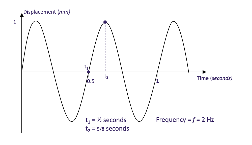
We want to know the velocity and acceleration of the body after ½ second ( ). Substituting these values into the equations gives:

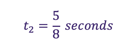

From this example, we can see that when the velocity is maximum, the acceleration is zero, and when the acceleration is maximum, the velocity is zero.
So, you can’t really use the same technology to give both velocity and acceleration; their magnitudes are very different, and they are 90ᴼ out of phase with each other. Each needs its own technology, but because they are interrelated, you can use one technology to derive both velocity and acceleration. It is shown how a little later.
How Do Vibration Sensors Work? (Velocimeters vs. Piezoelectric Accelerometers)
Velocity
A common way to measure velocity is to use a magnet suspended within a coil of wire. When the magnet is moving, a voltage is generated across the ends of the coil. The faster the coil moves, the higher the voltage.
The velocity of vibration is maximum when the oscillation passes through the zero reference, and this is when the voltage output from the magnet and coil is maximum.
The instrument that purely measures velocity is called a velocimeter, and not an accelerometer.
Acceleration
A common way to measure acceleration is to use a piezo-electric crystal under pressure from a weight. When the sensor receives a shock force (i.e., an impulse), the weight stays still whilst the sensor accelerates, causing the crystal to deform. When you deform a crystal, a charge is generated across its opposite faces, which a charge amplifier then amplifies into an output voltage. The picture below reasonably illustrates the principle, where the inertial mass is “free” to move and apply a force to the crystal, causing it to deform.
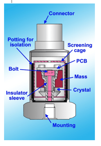
The maximum charge generated by the crystal is when it has been deformed the most, which occurs when the acceleration is maximum, i.e. at the peaks and troughs of the oscillation.
This instrument is correctly called an accelerometer.
Why Use an Accelerometer to Measure Vibration Velocity?
Well, it’s back to the calculus. We saw that you can determine Acceleration by differentiating the equation for Velocity.
To get back to Velocity when you have Acceleration, you need to integrate the acceleration equation:

For the sinusoidal vibration that we have been analysing, the above integral returns:

as before.
In electronics, a capacitor across the input of a signal-amplifier circuit gives us an integrated output. In software, an integration function is applied to the acceleration to derive the velocity. So, when we see that an accelerometer is being used to give a velocity measurement, we know that some transformation of acceleration to velocity is being done in the sensor, or the signal conditioner.
The opposite can also apply when a velocity sensor gives us an acceleration output derived from a calculation. To do this, a capacitor is used in series with the input signal to act as an electronic differentiator, or a derivative function is applied in software to achieve the same outcome.
Explore our range of accelerometers for condition and vibration monitoring applications.
Multiple Output Signal Conditioning
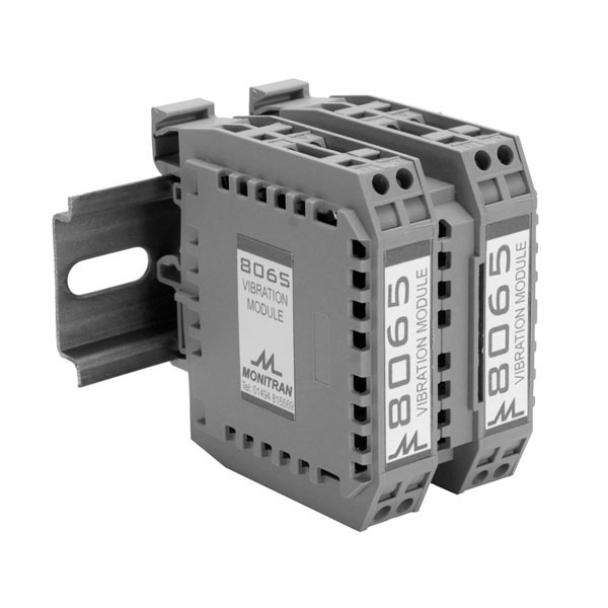
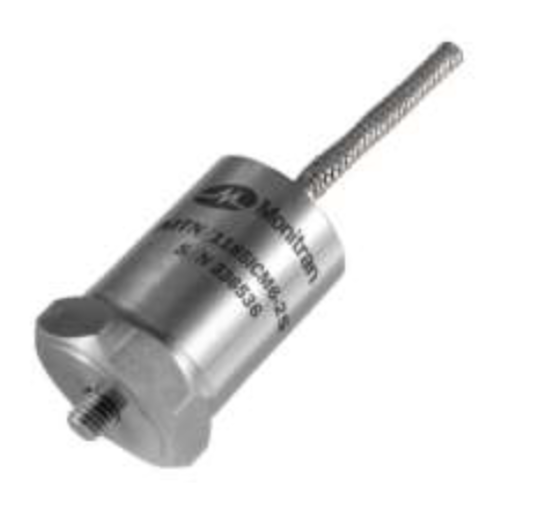
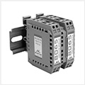
The Monitran MTN/8065 Tri-Output Vibration Interface Module takes the raw AC output signal from an accelerometer and gives 3 concurrent measurements:
- RMS Velocity (0 – 10 volt output)
- Acceleration (mV/g)
- Enveloped g Output (0 – 10 volt output)
What is Enveloped g and FFT in Bearing Fault Detection?
What is FFT?
Frequently Asked Questions
What is the difference between measuring vibration velocity and acceleration?
Vibration velocity (measured in mm/s) reflects the fatigue and destructive force of general machine unbalance, looseness, and misalignment between 10 Hz and 1 kHz. Acceleration (measured in g or m/s²) captures high-frequency forces, making it essential for detecting gear meshing problems and bearing defects above 1 kHz.
What is enveloped g in vibration analysis?
Enveloped g is a signal-processing technique that uses Fast Fourier Transform (FFT) and filtering to isolate repetitive, high-frequency impact spikes caused by microscopic bearing faults (such as raceway fractures) from background machine noise.
How can an accelerometer measure vibration velocity?
Because velocity is the mathematical integral of acceleration, an accelerometer can provide a velocity output either through internal analogue integration circuitry (using a capacitor circuit in the amplifier) or digitally via software algorithms.
Further Information on Vibration Monitoring and Vibration Sensors
If you would like to learn more about vibration measurement and using accelerometers to monitor the condition of your plant and machinery, please send any questions via our contact page here or call us directly on 1300 236 467.
A member of our expert team will gladly answer any questions that you may have.