Summing or Averaging Load Cell Signals
It is common for multiple load cells to be used to measure the weight of an item. For example, a tank, silo, or platform with 4 legs with a load cell under each leg. Or a weighing platform may consist of a square plate with load cells positioned under each corner.
The output values of the 4 load cells need to be averaged in the field, and a single representative load cell signal output to be sent to the display or signal transmitter.
We will explore two methods of achieving this: the traditional analogue electronics method and the more modern digital metho of summing and equalising load cells.

Traditional Analogue Method of Summing and Equalising Load Cells
This is achieved with a load cell summing junction box, which is sometimes referred to simply as a junction box.
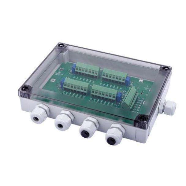
However, it is much more than just an empty junction box for you to join load cell wires, so that you do not have to run 4 sets of cables to the control cabinet or display. It incorporates the electronics required to average or sum the outputs from your load cell into a single representative output.
Inside the junction summing box you will see the relevant screw terminals labelled on a PC board. There is an adjustment potentiometer for each connected load cell. The potentiometer enables you to adjust the sensitivity of the 4 load cells to be equal, so that under an identical load they give the same output, resulting in a more accurate reading than you otherwise would have.
In addition to combining load cell signals, the junction box also serves to distribute the required excitation voltage to each of the load cells.
Load cell junction boxes are also available with 6 and 8 channels to support a system with a higher number of load cells.
Since load cell junction boxes are field mountable, it is possible to have an explosion proof enclosure for use in hazardous areas. They can also provide a moisture ingress protection level of IP67.
Set Up Procedure and Adjustment of Load Cell Summing Junction Box
Let us take a flat platform with a load cell under each corner as an example.
Turn all potentiometers anticlockwise at least ten turns until all are at the end stop (they click when rotating past the end point)
Connect all load cells. Apply an excitation voltage. Mount a test weight on top of a load cell or place the weight in the corner of the platform and then record the output reading. You can record either the output in millivolts on your multi-meter, or whatever the amplifier/readout meter is indicating, such as kilograms etc.
Repeat this procedure for each load cell or corner. It does not matter if the output values are not calibrated at this stage, it is important to record the output value from each load cell and not to alter any potentiometers at this time.
Pick the lowest reading of the 4 load cells and leave its potentiometer alone. It is recommended that you seal this potentiometer with some locking glue. Now position the test weight on another load cell and adjust the potentiometer associated with that load cell in a clockwise direction, until the output reading is the same as the output recorded from the load cell with the lowest reading.
Repeat step 4 on the remaining 2 load cells or corners, ensuring that when the test weight is applied to each load cell its potentiometer is adjusted until the output from the junction box is the same as the outputs from the load cells mentioned in step 4. Seal all the potentiometers with locking glue. Now all the load cells have been normalised to give an equal contribution to the total output reading of weight. On a platform scale you should be able to place the test weight in the centre and still get the same output value.
Now you have all 4 load cells installed in the system. Remove all weights and set the zero points on your indicator or amplifier. Using test weights, you can begin calibrating the system. Set the amplifier or indicator output to read the correct weight of the test weight. It should indicate the value of the test weight only and not the weight of the system’s tank, hopper, etc.. Recheck the zero and loaded weight, repeating with different weights up to the maximum weight of the system’s design. Next, remove all test weights. With the system unloaded adjust the tare of the amplifier or display to give a zero output. Add the test weights and confirm correct readings one last time.

Modern Digital Method of summing and Equalising Load Cells
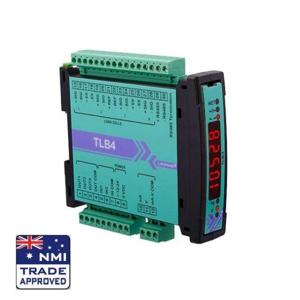
The Laumas TLB4 four channel transmitter can equalise and sum up to 4 load cells. It provides all the load cells with the required excitation voltage, and it reads back the returned signals, to transmit one single representative load cell output.
The summing and equalisation procedure can be carried via the on-board LED display and keypad.
This device performs that function of:
Load cell equalization board
Load cell transmitter
Load cell display

Using Load Cells With 6 Core Cables
6 core cables are used instead of 4 core cables to compensate for voltage drop caused by longer cable runs. In this case the additional 2 cores share the S+ and S- sensor terminals, so there is no special junction box required for these load cell cables.
Remember to use proper load cell cables, as these are an integral part of the load cell circuit and can affect the accuracy and reliability of readings.
Should you need technical support or advice, please contact ADM Systems team to discuss your application.