Selecting the Best Torque Transmitter for Your Application
Torque sensors are designed for rotating and non-rotating applications. To measure torque, several technologies can be used to detect the elastic deformation of the element under strain, e.g., strain gauge, inverse magnetostriction, inductance, phase shift, capacitance, etc.
Strain gauge and inverse magnetostriction technologies will only be considered at this stage, with comparison of accuracy, contact or non-contact electrical circuitry, and asymmetric forces applied to the sensor’s shaft.
This discussion aims to help you better understand how torque is measured and help you choose which torque sensor and measuring technique is best for your application or budget.
For in-line rotating and non-rotating torque measurements these are:
- Strain Gauge Torque Transducers
- High accuracy <0.5%
- Highest cost
- Contact electronic circuitry
- Inverse Magnetostrictive Torque Transmitter
- Low accuracy >1%
- Cost effective
- No additional load cell transmitter required
- Non-contact electronic circuitry
- Highly immune to asymmetric forces on the shaft
For non-rotating torque measurement of the reaction force on a lever arm:
- Single Point Load Cell Torque Transducer
- Lowest cost point
- High accuracy <0.1%
- Needs mechanical design implementation
- Signal results require calibrating in terms of Nm
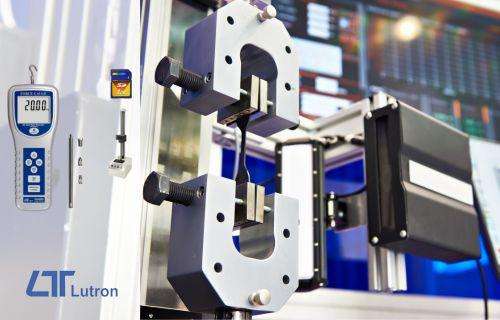
Strain Gauge Torque Transducers

The more traditional method of measuring torque is using a strain gauge circuit, in a similar manner to the way a load cell measures force, which is bonded to a precision machined element (round or flat) and measures the deformation of the element, which is directly proportional to the torque.

For the non-rotating strain gauge torque sensor, the strain gauge wiring is easily terminated directly on the external connector.
However, in the case of rotating shaft transmitters for revolutions of less than 4,000 to 5,000 RPM, sliprings are used to provide an electrical connection with the strain gauge’s Wheatstone Bridge.
Sliprings are subject to wear & tear, requiring periodic maintenance and this should be considered in the decision-making process.
Strain gauges are fragile in nature and if stretched beyond their elastic limit, measurement errors will result.
Click on the following link to see an example of a strain gauge torque transducer offered by ADM:
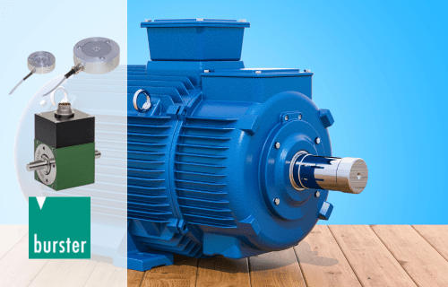
Inverse Magnetostrictive Torque Transmitter

This non-contact method of determining torque applied to a shaft is considered more reliable and robust than strain gauge implementations. It is also more cost effective, but not as accurate as strain gauge technology. However, not every application demands high accuracy.
The electronics inside the torque transducer induces a magnetic field onto the shaft at a predetermined point.
At a specific distance further down the shaft, a sensor measures the magnetic field strength. The amount of torque that is applied to the shaft has a direct influence on the strength of measured magnetic field.
Because the onboard electronics transmits a standard usable analog signal such as 4-20mA, 0-10V or 0-5V, there is no need for an additional external load cell transmitter. Thereby, offering a further cost saving on the installation.
Being non-contact, magnetostrictive torque sensors are more tolerant of torque overload and asymmetric forces applied to the shaft.
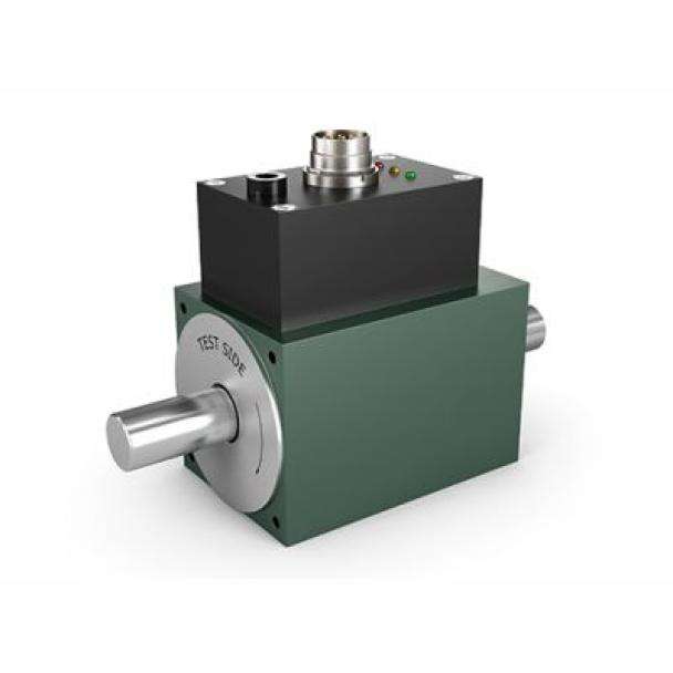
Click on the following link for an example of an inverse magnetostrictive torque transmitter.
Burster 8661 Torque Transmitter
When deciding on what type of technology best suits an in-line torque sensing application, there are several parameters that need to be considered, for example:
- Cost vs. accuracy
- Accuracy vs. reliability & overload tolerance
- Integrated output electronics vs. need for signal conditioner
- Wear & tear vs. low maintenance
Load Cell Design Torque Transducer
The torque transmitters we have already mentioned use an in-line shaft coupling arrangement, which can be difficult to implement, as mounting space must be made between the force driver and the load for the transmitter and its shaft couplings.
In an existing installation this can be difficult.
The load cell approach requires the systems integrator to fit a lever arm and may be more easily implemented than a shaft-type torque transducer.
Here is a very simple design that ADM engineered for a client using a single low-cost S-Type load cell to measure the starter motor torque of a jet aircraft.


Do not hesitate to contact ADM Instrument Engineering if you need to measure torque in your application. A member of our expert team will help you select the most cost effective and technically suitable solution.